By Lawani Wariebi, CMRP, Maintenance Manager, Japeils Compression Nigeria Ltd.
June 2021
Abstract:
Based on the decline of Plant availability from 95% at January 2015 to 83% at July 2016. PARETO Analysis was conducted on all the failures recorded at the Izombe Gas Compression Plant on all eight gas compressor packages for this period. With a total of 156 failures and a maintenance cost of $240,685.23, 5 WHYs RCA methodology was use to investigate the root causes of frequent failures causing equipment downtime. Corrective actions were recommended to curtail repetitive failures. These led to improved Plant reliability, increased the Plant availability to 97% as at February 2017, and reduced Plant maintenance cost by 30%. After implementation of the Pareto report, Plant monthly availability rose from 83% as at July 2016 to 97% at February 2017.
1.0 SCOPE:
The report covers the use of PARETO Analysis to investigate the reduction in equipment reliability, which resulted in declining Plant Availability. This report shows graphical analysis of 156 failures with total maintenance cost of $240,685.23 at the Izombe Gas Compression Plant on all eight-gas compressor packages with a combined 24,000HP from January 1st, 2015 to 1st of August 2016. 5 WHYs RCA methodology was use to investigate root cause of each failure and corrective actions recommended to curtail repetitive failures.
2.0 OBJECTIVE:
This report shows collating series of failure histories ranking them into different categories at the Izombe Compression Gas Plant. Each failure was analyzed graphically using pie and bar chart to show graphical representation of failure frequency and cost analysis.
3.0 OVERVIEW OF ADDAX IZOMBE GAS COMPRESSION PLANT:
The purpose of this project installation is to flare-down 48 mmscfd at the Addax Izombe Flow station enabling ADDAX to comply with the Nigerian government flare out policy. The associated gas is received from the Izombe Flow station at 100 psig at the inlet to the Flare down Gas Compression Station compressing the gas up to 1400 PSI for gas lifting and up to 3500 PSI for gas injection.
The associated gas is received at 100 psig, 48 mmscfd and 120 oF at the inlet to the Gas Compression Station separator (V-201) via a single gas inlet pipeline (pipeline by others). A valve station is supplied at the gas supply pipeline interface to provide manual and automatic emergency shutdown isolation of the LP suction header from the inlet pipeline, with automatic and manual blowdown to the existing flare system.
Six (6) inlet compressors (LP compressors) compresses the associated gas from 100 psig to 1400 psig. The LP compressors consist are skid mounted, natural gas engine driven reciprocating compressor packages (as per equipment list mentioned below). each compressor package. Each compressor has a manual start-up bypass valve, and a manual discharge blowdown valve.
The purpose of the gas compression system is to increase the pressure of the inlet gas 48 MMSCFD, 100 PSI up to 1400 PSI to meet the Gas lift requirement in the Low Pressure compressors (6 units). 14.7mmscfd will be tapped for gas lifting then increase the pressure of the remaining gas of 33.3mmscfd up to 3500 PSI to meet the gas injection requirement.
|
2. Major Equipment Compression
|
Driver
|
|
C-201
|
LP Compressor Unit 77020
|
Waukesha L5794LT / Ariel JGK-4
|
|
C-202
|
LP Compressor Unit 77018
|
Waukesha L5794LT / Ariel JGK-4
|
|
C-203
|
LP Compressor Unit 74155
|
Waukesha L7042GSI / Ariel JGK-4
|
|
C-204
|
LP Compressor Unit 74183
|
Waukesha L7042GSI / Ariel JGK-4
|
|
C-205
|
LP Compressor Unit 73586
|
Waukesha L7044GSI / Ariel JGK-4
|
|
C-206
|
LP Compressor Unit 77779
|
Waukesha L7044GSI / Dresser
5HOS-4
|
|
C-207
|
Booster Compressor Unit 315547
|
Waukesha L7042GSI / WH64
|
|
C-208
|
Booster Compressor Unit 315548
|
Waukesha L7042GSI / WH64
|
|
A-301A/B/C
|
1st/2nd/3rd Stage Discharge Cooler (included with C-
201)
|
|
A-302A/B/C
|
1st/2nd/3rd Stage Discharge Cooler (included with C-
202)
|
|
A-303A/B/C
|
1st/2nd/3rd Stage Discharge Cooler (included with C-
203)
|
|
A-304A/B/C
|
1st/2nd/3rd Stage Discharge Cooler (included with C-
204)
|
|
A-305A/B/C
|
1st/2nd/3rd Stage Discharge Cooler (included with C-
205)
|
|
A-306A/B/C
|
1st/2nd/3rd Stage Discharge Cooler (included with C-
206)
|
|
A-307A/B
|
Discharge Cooler (included with C-207)
|
|
A-308A/B
|
Discharge Cooler (included with C-208)
|
|
V-301A/B/C
|
1st/2nd/3rd Stage Suction Scrubber (included with C-
201)
|
|
V-302A/B/C
|
1st/2nd/3rd Stage Suction Scrubber (included with C-
202)
|
|
V-303A/B/C
|
1st/2nd/3rd Stage Suction Scrubber (included with C-
203)
|
|
V-304A/B/C
|
1st/2nd/3rd Stage Suction Scrubber (included with C-
204)
|
|
V-305A/B/C
|
1st/2nd/3rd Stage Suction Scrubber (included with C-
205)
|
|
V-306A/B/C
|
1st/2nd/3rd Stage Suction Scrubber (included with C-
206)
|
4.0 INTRODUCTION TO THE GAS COMPRESSION PACKAGE:
“Compression” is used in all aspects of the natural gas industry, including gas lift, reinjection of gas for pressure maintenance, gas gathering, gas processing operations (circulation of gas through the process or system), transmission and distribution systems, and for storage, two basic types of compressors are used: Reciprocating and centrifugal compressors. Reciprocating compressors are usually driven by either electric motors or gas engines, whereas centrifugal compressors use gas turbines or electric motors as drivers.
4.1 Reciprocating Compressors
A reciprocating compressor is a positive displacement machine in which the compressing and displacing element is a piston moving linearly within a cylinder. The reciprocating compressor uses automatic spring-loaded valves that open when the proper differential pressure exists across the valve.
Figure 1 describes the action of a reciprocating compressor using a theoretical Pressure – Volume (PV) diagram. In position A, the suction valve is open and gas will flow into the cylinder (from point 1 to point 2 on the PV diagram) until the end of the reverse stroke at point 2, which is the start of compression. At position B, the piston has travelled the full stroke within the cylinder and the cylinder is full of gas at suction pressure. Valves remain closed. The piston begins to move to the left, closing the suction valve. In moving from position B to position C, the piston moves toward the cylinder head, reducing the volume of gas with an accompanying rise in pressure.
The PV diagram shows compression from point 2 to point 3. The piston continues to move to the end of the stroke (near the cylinder head) until the cylinder pressure is equal to the discharge pressure and the discharge valve opens (just beyond point 3). After the piston reaches point 4, the discharge valve will close, leaving the clearance space filled with gas at discharge pressure (moving from position C to position D). As the piston reverses its travel, the gas remaining within the cylinder expands (from point 4 to point 1) until it equals suction pressure and the piston is again in position.
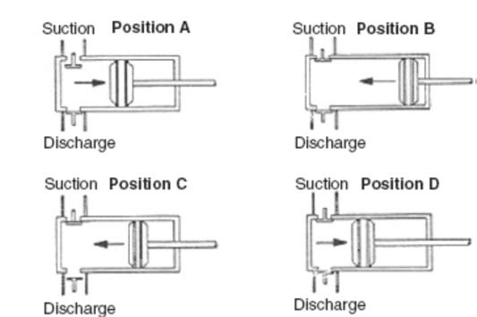
Figure 1.
5.0 PARETO ANALYSIS:
Pareto Analysis is a technique used for decision-making based on the Pareto Principle, known as the 80/20 rule. It is a decision-making technique that statistically separates a limited number of input factors as having the greatest impact on an outcome, either desirable or undesirable. Pareto analysis is based on the idea that 80% of a project's benefit can be achieved by doing 20% of the work or conversely 80% of problems are traced to 20% of the causes.
For this analysis, the failure history is gotten from Exterran SAGE 300 ACCPAC ERP CMMS, 156 recordable failures occurred from 1st of January 2015 to 1st of August 2016 for the eight Gas Compression Packages, with total maintenance cost of $240,686.23 these includes labor and items only.
Pareto was conducted in graphical form to determine the equipment with the highest and lowest frequencies, percentages, maintenance cost per failure. Further analysis was conducted to find out the failure with the most: Frequency, Percentages and Maintenance Cost.
5.1 LIST OF FAILURES IN THE CMMS FROM 1st January 2015 to 1st August 2016:
1. LOW EXHAUST CYLINDER TEMPERATURE
2. FAILED CYLINDER HEAD
3. ENGINE OIL LEAKAGE
4. LOW ENGINE OIL PRESSURE
5. HIGH ENGINE JACKET AND AUXILLIARY WATER TEMPERATURE
6. ENGINE LOSS OF POWER AND FLUCTUATING RPM
7. ENGINE UNDERSPEED
8. ENGINE COOLANT LEAKAGE
9. COMPRESSOR PACKING AND LACK OF LUBRICATION FAILURE
10. FAILED PRESSURE SAFETY VALVE
11. LOW COMPRESSOR OIL PRESSURE
12. VIBRATION SWITCH FAILURE
13. HIGH COMPRESSOR TEMPERATURE AND DISCHARGE TEMPERATURE
14. DAMAGED PUSHED ROD
15. LEVEL CONTROLLER FAILURE
16. DNFT NO FLOW FAILURE
17. IGNITION AND CEC FAILURE
18. DAMAGED ROCKER ARM COVER
19. FAILED AIR STARTER MOTOR
20. LOW BATTERY VOLTAGE
21. FUEL SHUT OFF VALVE FAILURE
22. EXHUAST LEAKS
23. RUPTURED HOSE
24. DAMAGED FAN BELT
25. PRE-LUBE PUMP FAILURE.
These failures are traced to factors such as; Temperature, Pressure, Leaks, Speed, Vibration, Misalignment, Restrictions to flow, excessive tensile force, balance, grounding and age.