By Fawaz Alkhuliawi, CMRP, VMA, Internal Audit, Maintenance Engineering Specialist, Saudi Aramco
June 2021
Most industries deal with shell and tube heat exchanger and double pipe heat exchanger types, which are very crucial to plant operation. These types during operation, loss its duties and fails due to one or more factors such as following:
- Excessive fouling
- Air or gas entrapment (binding resulting) from improper piping installation or lack of suitable vents
- Differences between operating conditions and designing conditions
- Misdistribution of flow in the units
- Excessive clearances between the baffles and shell and or tubes due to corrosion
During heat exchanger operation, every heat exchanger shall be visual inspected externally to at least every 5 years or at the same interval as the required internal or on-stream inspection. Whichever is less. Any signs of leakage should be shutdown the unit and investigated. Inspection for corrosion under insulation (CUI) shall be considered for external insulated vessels subject to moisture exposure for temperature operating between 25°F (– 4°C) and 250°F (120°C).
Internal and on-stream inspection shall not exceed one half the estimated remaining life of the heat exchanger. This should be in accordance to corrosion rate or 10 years, whichever is less. The unit that is not adequately protected from corrosive environment shall experience significant internal corrosion while idle and should be carefully reviewed when setting inspection.
On line inspection flanged leakage and UT-NDT thickness and offline inspection shall be Periodic monitoring for; Corrosion by various methods, Fouling, Leaking tube joint, Structural and vibration damage, Sacrificial Anodes, thermal damage.
On-stream Inspection:
The heat exchanger cannot be internally inspection for following situations
1. Lack of access to internally inspect heat exchanger due to size or configuration
2. The general corrosion rate of heat exchanger to be less than 0.005 inch (0.125 millimeter) per year and the estimated remaining life is greater than 10 years (the operating temperature of heat exchanger shell does not exceed the lower temperature limits for creep rupture range of the heat exchanger material)
3. The heat exchanger is not subject to environmental cracking or hydrogen from the services.
4. The heat exchanger is not subject to environmental cracking or hydrogen from the services.
In lieu of internal inspection, a thorough examination shall be performed using ultrasonic thickness measurements, or radiography or other appropriate NDT methods to measure metal thicknesses and seams integrity. The inspector shall be provided access to all parts of heat exchanger (heads, shell and nozzles), thus a comprehensive assessment can be conducted.
The thickness measurement locations (TMLs) are established general and localized corrosion rates in different sections of the heat exchanger. The thickness measurement can be measured using NDT methods by scanning radiography profile or ultrasonic. Calculate the remaining life using this formula:
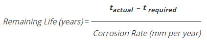
tactual = the actual thickness, in inches (millimeters), measured at the time of inspection for a given location or component.
t required = the required thickness, in inches (millimeters), at the same location or component as the Tactual measurement, computed by the design formulas (e.g., pressure and structural) before corrosion allowance and manufacturer’s tolerance are added.
Testing Requirement
In order to check the integrity of tube to tubsheet joint without prior shutdown he unit, the following Table-1 demonstrates different type of TEMA heat exchanger classifications that might use for assessing the required action course for maintenance (Ex. Using test ring for hydrotesting).
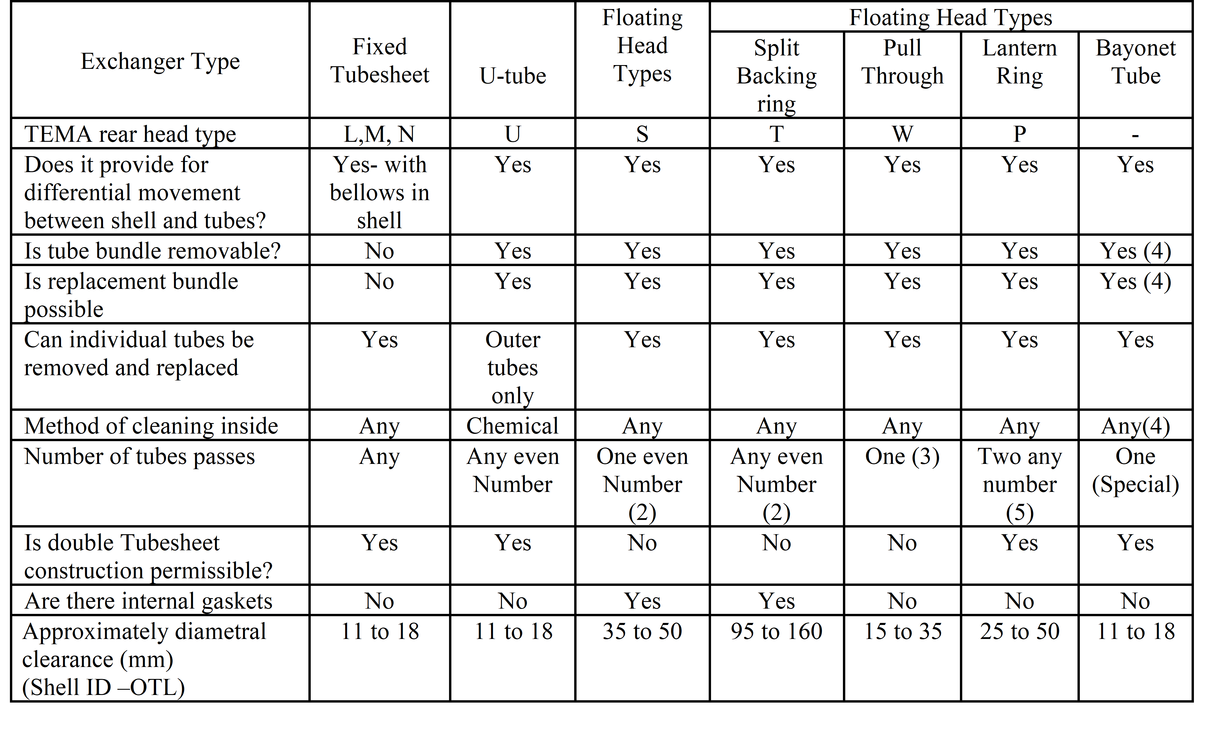
Table 1: Types of shell and tube heat exchangers (Summary of features, reference to tTEMA heat exchanger Nomenclature)
Note:
- External mechanical cleaning possible only with square or rotated square pitch or unusually wide triangular pitch
- One pass construction required packed gland or bellows at floating head
- Tube side nozzles must be at stationary end for two passes
- Assumes tubesheets for outer tubes not welded to shell
- Axial nozzle required at rear end for odd number of passes
All heat exchangers shall be tested with precaution to hydrostatic test pressure for heat exchanger built prior year 1999’s Code edition is to use 1.5 times of MAWP (Maximum allowable Working Pressure), while the heat exchanger built in year to 1999’s and consequent editions shall be tested at pressure equal to 1.3 times MAWP.
Cleaning Tube Surfaces
The heat exchange shall have accessibility for inspection, maintenance and cleaning in order to maintain the heat transfer efficiency. The cleaning methods shall be:
- Chemical methods by circulating hot wash oil or light distillate at high velocity to remove salts.
- Mechanical methods by depending on services of high-pressure water jet, scrapers, rotating wire brushes, sliding brushes or ball (the ball may be used in online services)
Verify chemicals effectiveness/inhibition prior to cleaning, monitor cleaning carefully. Before start cleaning the heat exchanger, all external conditions should be reported. Examples of the external condition: Structural appearance, Distortion indication by non-uniform gasket compression, Flange/Tubesheet distortion, Corrosion, erosion, Tube damage and deterioration.
The appropriate cleaning method can be selected based on degree of fouling, heat exchange material and system components and contact chemical cleaning compounds. The chemical disposal should be adherence to Loss prevention supervision.
Gasket Selection and Replacement
For type TEMA-R (For the generally severe requirements of petroleum and related processing applications) heat exchanger, metal jacket or solid gasket shall be used internal floating head joints for 300 psi and for joints in contact with hydrocarbon. Take into consideration to minimize the galvanic corrosion.
For TEMA type C (For the generally moderated requirements of commercial and general process applications) and B (For general process service) heat exchanger of designing pressure 300 psi and below, a composition gasket may be used for external joint, unless temperature or corrosive nature of constrained fluid indicates otherwise. Metal jacket filled or solid metal gaskets shall be used for all joints for designing pressures greater than 300 psi and for internal floating head joints.
Bolt Torque Procedure
All heat exchanger bolts should be evenly tightened with specified torque rate in compliance OEM. Adhering to tightening procedures will minimize the impact of cyclic thermal expansion/contraction. The gasket surface shall be cleaned and utilize proper gasket type. The sequence and torque rate shall be followed as shown in figure 1, and Table 2.
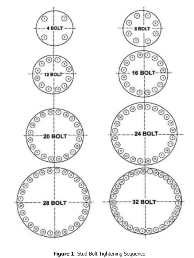
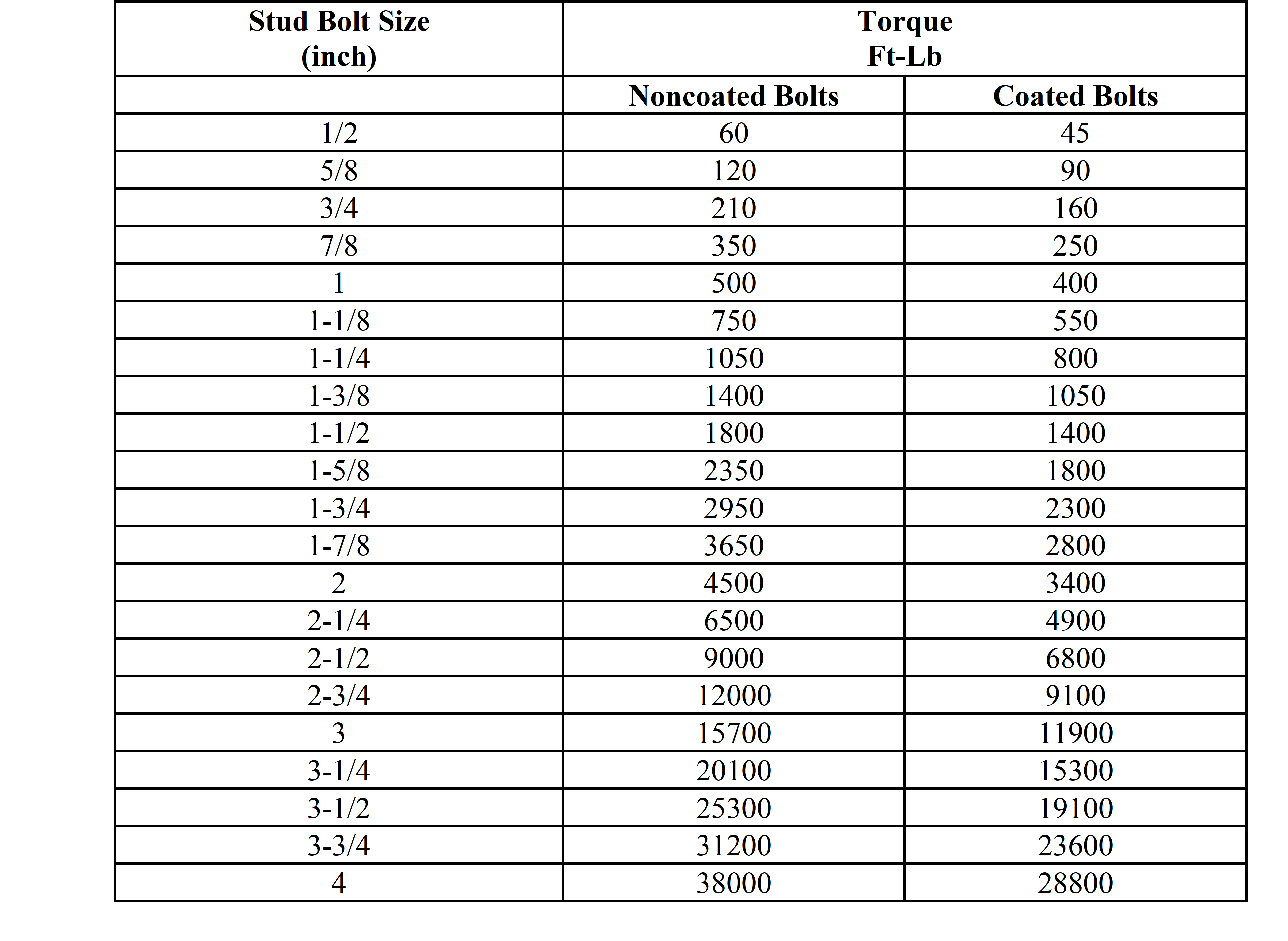
Table 2: Torque Values for Low-Alloy Steel Bolting
Notes:
- Torque values are based on 50,000 psi prestress on stud bolts and Friction Factor of 0.16 for noncoated surfaces and 0.12 for new coated surfaces. A combination of various elements such as the conditions of the threads, the condition of the flange to the nut bearing surface and the type of lubricant used, makes up the friction factor which can vary from .04 to .20 or as much as 500%.
- Torque values for stainless steel or other alloy stud bolts can be obtained by multiplying the ratio of the specified minimum yield strength (SMYS) of stainless steel stud bolts to A193 B7 stud bolts. The SMYS values for all bolting materials are listed in ASME B31.3 code (Note: SMYS depends on grade, class and size).
Shop Activities
In order to cover shop maintenance activities for all types heat exchangers, operation side shall first go through action to avoiding shutdown the unit. The heat exchanger with removable tube bundle may be gradually shutdown of low of the hot medium and then cold medium. If it necessary to stop the cold fluid first, the hot medium be stopped at once. For fixed bundle heat exchanger, both mediums should be stopped in such a manner to minimize the differential thermal expansion between shell and tube. By passing may incorporate for this purpose.
The heat exchanger shall be cleaned for inspection, then maintenance side to repair in-situ as per inspection findings. For complete retubing scope of work, the heat exchanger is highly recommended to be sent to Shop for proper handling. Every plant shall maintain and fabricate Test Rings for conducting tube test in-situ. For delivering the heat exchanger to Maintenance, operation should depressurize and purge the unit from any entrapped gases.
Retubing Criteria and Alternatives
If all Field action fails to revamp heat exchanger in-situ with attempt to role leak and exceeding plug percentage (usually don’t exceed 10 % from total tube numbers). The following are checkpoints to be considered for retubing:
- A removal of the tube bundle requires the joint to be first marked with chisel
- Before making a decision of retubing, Proponent shall prepare safety plan for handing unit weight and unit accessibility (Figure 2 exhibit retubing process for shell and tube heat exchanger).
- Determine the accepted level of heat exchanger performance and minimum tube wall thickness requirement (Inspection shall perform MFL/eddy current/IRIS to generate a full report for tubes condition).
- Retube if there is a need to comply for any process change or changing tube material to increase corrosion resistance (Tube sleeving is an option when the tube replacement is needed).
- The one-piece taper plug should be tapered to an angle of about 5° to create the required interference fit between the plug and the inner surface of the tube.
- Use only enough forces to contain the leak. Avoid using excessive force that may result in ligament deformation
- Pinch a hole in the tube before plugging, this will allow air venting that if not vented properly to force the plug to fly out.
- Check cleanliness of finned surface. If they are fouled, external cleaning shall be performed.
- Heat exchanger cleaning can be cleaned by water (hydrojetting), chemical, or mechanical.
- Mechanical Cleaning should carefully taken care to avoid tube damage.
- Cleaning compound when using chemical cleaning must be compatible with the metallurgy of the exchanger.
- For plugging the tubes, a new tube fluid velocity and pressure drop should be checked using following formula.
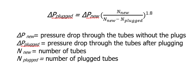
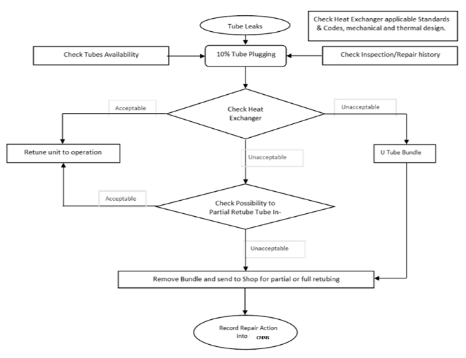
Figure 2: Guideline flowchart for Retubing Heat Exchangers
References
API STD 510 Pressure Vessel Inspection Code: Maintenance Inspection, Rating, Repair, and Alteration
Tubular Exchanger Manufacturers Association (TEMA)